VHD DiscWorld
GE VHD Player Test (August 1981)

Home

The VHD Video Disc System | 3D Compatible Video | 1982 SMPTE Journal Article | VHD in America Part 2 | VHD News Clippings | Inside The VHD Disc System | Video Review Magazine's VHD Report | GE VHD Player Test (August 1981) | VHD In The U.K. | Dual-Standard NTSC/PAL/SECAM VHD | Review: Victor HD-7900 VHD Player | Review: Victor HD-9300 3D VHD Player | Comparing VHD/LD/CED | AHD: Audio/Advanced High Density

Popular Electronic's General Electric 1VHD3042W Video High Density Disc Player Test.
(August 1981)

General Electric VHD Player

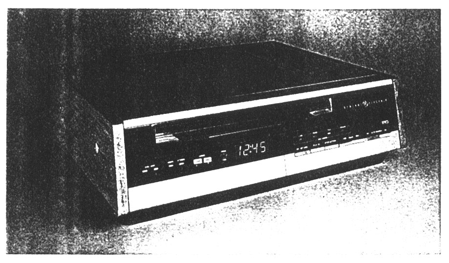
The Matsushita/JVC Video High Density (VHD) disc player is now off the drawing board and into hardware. Initial prototypes have been delivered to U.S. partner General Electric and Matsushita-owned Panasonic. The disc itself is smooth-surfaced, 10.2" in diameter. It is made from com-pression-molded PVC plastic, carbon black, a lubricant, and other additives. Spinning at a constant 900 rpm, it is designed to play one hour per side. Be-cause the force of the stylus on the disc is spread over more disc area than in the CED (Capacitance Electronic Disc) sys-tem, pressure on the surface is accord-ingly less. Stylus life, consequently, could amount to more than 1,000 hours, and recordings last for up to 10,000 plays. Dual audio channels can carry either full stereo or bilingual outputs.
Time-share picture and audio frames (54,000 per disc) are molded into the plastic as variable length pits of uniform depth, with tracking pits running along-side, and at right angles to them. The pickup head has only flat contact with the record, and may move freely over the disc's surface, permitting still pictures and forward and reverse slow mo-tion at 1/2, 1/4, 1/8, and 1/16 normal speed. Similarly, forward and reverse fast pic-ture search (with picture) is possible at 2, 3, 4, and 5 times normal speed in the forward mode, and 2 and 3 times normal in reverse.
There is chapter and time access, but no frame identification. This will come later-at added expense. Meanwhile, the reduced method of picture identifi-cation will locate any specific image within about 15 frames, and frame-by-frame motion control can quickly move the stylus arm into the exact position for the frame desired.
The disc player will be introduced in Japan in October of this year, in the U.S. in January of 1982, and in Britain six months after that. Here, the system is to be marketed under the General Electric, JVC, Panasonic, Sharp and Quasar brand names. Meanwhile, nego-tiations for first-run movies, various shows, and other entertainment and educational programs are in progress.

Block diagram of VHD player

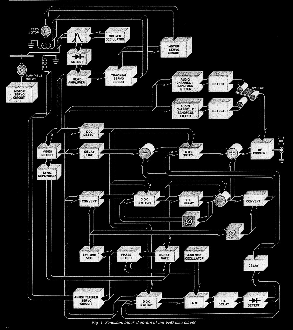
Operation. Since the system we inves-tigated is still a prototype, only a block
diagram (Figure 1) of the overall player was made available by General Electric. But even that is a good deal more than had been released previously.
The equipment is designed to operate in sequential steps, with lighted green indicators suggesting each succeeding step. The stylus is always in contact with the recording until play is completed, af-ter which the player automatically moves to the unload position, and the time clock resets to zero.
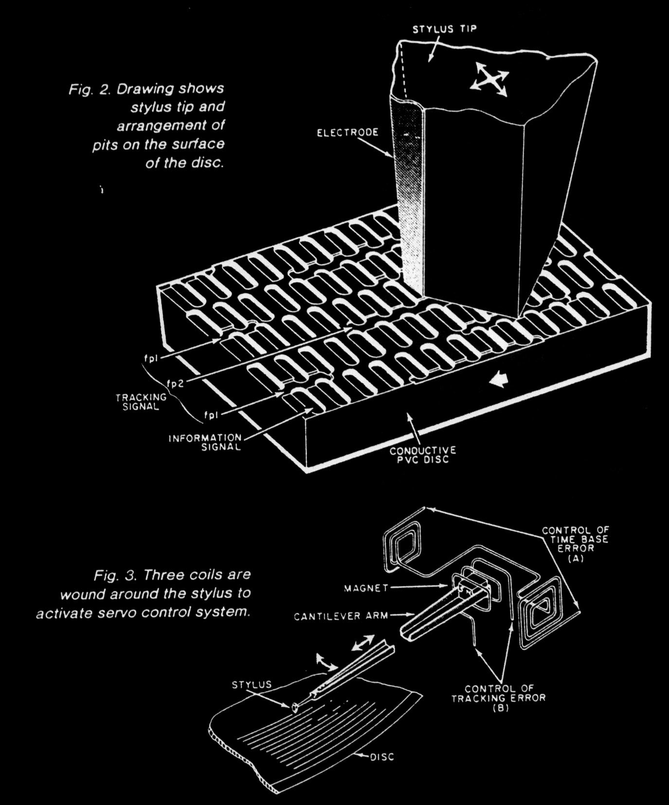
Variations in capacitance (equating to frequencies from 6.1 to 7.8 MHz) are picked up from individual pits on the disc by an electrode attached to the sty-lus and in physical contact with the disc (Fig. 2). A 915-MHz oscillator provides a carrier for the signal, which is then peak-detected so that it contains the to-tal video and audio information. A head amplifier receives this information and passes it to the tracking servo circuit, the dropout compensation (DOC) detec-tor, and the video detector. Additional signal paths lead from the tracking servo circuit to the motor servo circuit, and to the stylus coils on either side of the input.
Three coils guide the stylus (Fig. 3).
Coil B is wound around the center mag-net, but is not in contact with it; and the two A coils on either side of the center magnet are in electrical phase opposi-tion. Coil B controls the tracking error, while the A coils correct for time-base abnormalities. Thus, the stylus arm can move both transversely and longitudi-nally. This affords excellent stylus
tracking as well as operations such as frame scan

Stylus and tracking

Carrier levels on disc


The video detector supplies four sepa-rate outputs: one for the sync separator; another for two audio bandpass ampli-fiers and their detectors; a third to the DOC switch; and a fourth directly to the luminance delay line, which delays the luminance signal so it will be properly
timed with the chroma. Chroma burst (color sync) is carried conventionally on the back porch of the horizontal sync pulse and reaches the burst gate via the sync separator Chroma information, part of composite video, having been re-corded at approximately 2~56 MHz is up-converted to the NTSC standard 3.58 MHz via the 6.14 MHz voltage-
controlled oscillator. It is then passed to the dropout compensator switch, which is also supplied with feedback from the I H (horizontal line) delay line. Should a dropout occur in a line of video informa-tion, the previous line is automatically substituted.
The output from the 3.58-MHz oscil-lator goes to a phase detector and to the AM block, where input comes via anoth-er dropout compensator switch. From that point, three-way connections lead to composite video, the DOC detector, and to a feedback circuit from a second
I H delay line and its 1 H detector. This is part of a coincidence switching ar-rangement that permits the main DOC switch in the luminance processor to be activated just prior to final chroma addi-tion at the r-f converter.
The armstretcher servo circuit also bears mention. Its sensing signal is de-rived from the 3.58-MHz oscillator's phase detector, and from the incoming chroma burst gate. A phase-locked loop corrects both the frequency of the 6.14-MHz voltage controlled oscillator and the positioning of the stylus.
Analysis. G.E.'s and Matsushita's product falls somewhere between RCA's Capacitance Electronic Disc (CED) and the Philips/Magnavox/Pio-neer laser disc player. If recorded at only 1/2 hour per side, stop field/frame performance would theoretically be comparable to that of the laser unit. However, since each side is recorded for a full hour's play, any frozen picture occupies four fields or two frames. Where relatively still scenes are dis-played, there's very little movement visi-ble in the freeze frame. but where there is rapid motion in the picture, the jitter is rather pronounced.
Otherwise, this versatile player does essentially everything that the l/2~hour. per-side laser disc can do, with very little stylus and disc wear. Signal-to-noise ratios are much the same for Magnavox, RCA, and G.E./Matsushita at modula-tor outputs. There are, however, base-band ports for both audio and video in the G.E./Matsushita equipment that can reduce apparent noise through a more direct signal path. Stereo sound and bilingual channel reproduction are excellent, while picture quality probably comes very close to the 3.1-MHz design standard. Color rendition is exceptional for a player of this type.

GENERAL ELECTRIC MODEL IVHD3O42W VIDEO DISC

LABORATORY DATA
Parameter Measurement
Designed luminance bandwidth: 3.1 MHz
Designed audio bandwidth: 20 kHz. confirmed
Video S/N: 42 dB, confirmed
Audio S~N: 60dB claimed, 25 dB confirmed
Power drain: 30 W, confirmed
Acceptable power supply variation: 105-130 V ac. confirmed
Dimensions: 18.1W X 15.80 X 5.1"H
Weight (eat.): 28.5 lb